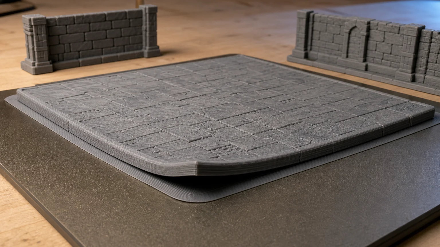
TLDR: Fix 3D printed terrain warping by identifying when the corners begin to lift. Immediate lift usually points toward a dirty build surface, an incorrect nozzle-to-bed distance, or a weak first layer. Curling that develops later is more likely to involve cooling contraction, drafts, material behavior, or demanding model geometry. Clean and calibrate first, add a brim if needed, stabilize the printing environment, and only then consider changing temperatures or splitting the model.
Large terrain pieces expose problems that a small miniature or scatter object may never reveal. A wide dungeon floor needs a consistent first layer across the bed, while a long wall can remain attached for hours before one end starts curling. Solving 3D printed terrain warping therefore requires more than turning up the bed temperature and hoping for the best.
The key diagnostic question is simple: did the corner fail during the first few layers, or did it lift after the print was already established? That timing tells you which group of fixes to try first.
Why terrain corners lift
FDM and FFF printers build parts from hot extruded material that cools after deposition. Cooling causes contraction, and uneven temperatures can produce internal stresses that distort a part or pull its edges away from the build plate. The visible result is often a raised corner, a bowed floor, or a wall that no longer sits flat.
Terrain is especially demanding because floors, roofs, foundations, and wall bases often combine broad flat areas with straight edges and sharp corners. A larger bottom contact area can improve adhesion when that entire area is printed correctly, but it also demands consistent bed contact from one side of the model to the other. UltiMaker’s FFF design guidance notes that bottom contact area matters for adhesion and that sharp bottom edges are more liable to warp than rounded corners.
A slightly distorted decorative rock may still be usable. A warped dungeon tile is less forgiving: it can rock on the table, open gaps between modular pieces, or push connected walls out of alignment. That makes modest corner lift worth correcting even when the print technically finishes.
Diagnose when the warping starts
Corners lift during the first layer
If a corner peels up almost immediately, treat the problem as first-layer adhesion until the evidence suggests otherwise. Watch the skirt and the perimeter around the terrain base. The lines should make continuous contact and join cleanly without remaining round and loose or becoming excessively flattened and rough.
A nozzle that is too far from the surface may lay down filament without enough contact. A nozzle that is too close can obstruct extrusion and create its own first-layer defects. Prusa identifies both build-surface cleanliness and correct nozzle-to-bed distance as important first-layer factors.
Corners lift after several layers
If the first layer looks sound but a corner rises much later, thermal conditions deserve more attention. The lower layers are being held near the bed while the upper part of the model cools under different conditions. Drafts, changing room temperature, material shrinkage, and the geometry of a long wall or floor can contribute to uneven stress.
Environmental temperature can affect FFF geometry. A NIST study of polycarbonate specimens observed thermal gradients and changes associated with environmental conditions in an open-chamber, heated-bed setup. NIST’s research on environmental conditions in FFF printing provides useful technical context, although its polycarbonate findings should not be treated as universal settings for PLA terrain.
Fix first-layer adhesion before changing everything else
Start with the low-risk checks. Remove the previous print according to the build-surface manufacturer’s instructions, let the surface reach an appropriate handling temperature, and clean it using the approved method for that plate. Avoid assuming that one solvent or cleaning routine is suitable for every coated, textured, glass, or polymer surface.
Next, confirm that the slicer has the correct printer, nozzle, filament, and build-plate profile selected. A proven manufacturer profile is a better starting point than an isolated temperature copied from someone using a different filament formulation or surface.
Then inspect bed leveling or the printer’s bed-mesh process and verify the first-layer calibration. Do not judge only the center of the plate. A large terrain floor may cross an area where the nozzle gap differs enough to weaken one corner even though the rest of the first layer looks acceptable.
Change one variable at a time and label the result. If you clean the plate, change bed temperature, alter cooling, add adhesive, and recalibrate simultaneously, a successful print will not tell you which correction mattered. For broader starting-point guidance, see printer settings for tabletop terrain, while keeping your machine and filament profile as the baseline.
Use a brim when the base needs more grip
A brim adds connected lines around the base of the model, increasing the area attached to the build surface. It is a practical next step for terrain with vulnerable corners, narrow wall bases, or a footprint that repeatedly begins peeling at the perimeter. Prusa specifically recommends brims as one way to increase adhesion area for parts prone to warping.
A brim is not a substitute for a poor first layer. If the brim itself is loose, stringy, or inconsistently squashed, return to cleaning and calibration. If it holds firmly but the terrain separates from the brim, inspect the slicer’s brim gap and profile rather than simply making the brim wider.
There is a cleanup tradeoff. A closely attached brim can leave a visible edge that needs trimming, especially around textured flagstones or connector recesses. Use enough brim to address the failure rather than automatically surrounding every piece with a large amount of extra material.
Control drafts and cooling conditions
Check the physical location of the printer before rebuilding the slicer profile. Air from an open window, door, fan, heater, or air-conditioning vent can cool one side of a large floor or long wall differently from the other. A printer may also behave differently overnight if the room temperature changes substantially.
Keep the environment reasonably stable for the duration of the print. That does not mean eliminating part cooling indiscriminately: cooling requirements depend on the material, overhangs, bridges, layer time, and printer setup. The goal is to remove accidental environmental variation before changing intentional slicer-controlled cooling.
Should terrain be printed in an enclosure?
An enclosure can limit drafts and reduce thermal shock, which can be helpful for higher-temperature, warp-prone materials. But it is not a universal upgrade for every terrain print. Prusa warns that PLA and PETG can be poor enclosure candidates in workflows where substantial print cooling is needed, while higher-temperature materials may benefit from the more stable environment.
For ordinary PLA terrain, address surface cleanliness, calibration, drafts, and brim use before assuming that an enclosed heated environment is necessary. If you already use an enclosure, follow the printer and filament manufacturers’ guidance on doors, ventilation, cooling, and safe operating conditions. An enclosure also does not replace any material-specific ventilation requirements.
Material choice changes the troubleshooting order. PLA, PETG, ABS, ASA, polycarbonate, and other filaments do not share one ideal bed temperature, fan setting, or enclosure strategy. If reliability is the priority, begin with a supported filament profile and consult the terrain filament comparison before changing material purely to solve a settings problem.
Review the terrain model’s footprint and corners
When the printer and first layer are reliable but one particular file keeps failing, examine the model rather than endlessly tuning the machine. Sharp lower corners concentrate the failure at an easy place for peeling to begin. Rounded or chamfered lower corners may reduce that risk when the design permits, consistent with UltiMaker’s FFF design guidance.
This does not mean rounding visible tile edges that must align on a gaming grid. A designer may instead modify a hidden underside corner, add removable adhesion tabs, adjust the base structure, or divide the footprint while preserving the playable dimensions. Connector clearances and mating faces should remain consistent.
Long walls present a related problem. Even when their total area is not enormous, they place vulnerable ends far apart and can amplify a small amount of lifting into a visible bow. Orienting the wall differently may help if the bed has a known weak area or receives a one-sided draft, but rotation is a diagnostic step rather than a guaranteed cure.
When to split a large floor or wall
Splitting a model is reasonable when the printer handles other pieces correctly but one oversized floor repeatedly warps despite a sound first layer and stable environment. Smaller modules reduce the uninterrupted span that must remain flat and may fit more consistently within the printer’s best-performing bed area.
The cost is additional seams, assembly work, and possible alignment errors. For modular terrain, a deliberate split along grid lines, stone joints, beams, or connector boundaries is usually more useful than an arbitrary cut through visible detail. Test the joint tolerance with a small section before committing to a whole set.
A practical troubleshooting order
- Note exactly when and where the lift begins.
- Clean the build surface using its manufacturer-approved method.
- Confirm the correct printer, plate, nozzle, and filament profiles.
- Verify leveling, bed mesh, and nozzle-to-bed distance across the model’s footprint.
- Reprint a small first-layer test in the affected area.
- Shield the printer from accidental drafts and large ambient changes.
- Add a brim if the calibrated first layer still needs more adhesion area.
- Review material-specific bed and cooling guidance before changing temperatures.
- Inspect sharp lower corners, narrow wall bases, and oversized uninterrupted spans.
- Split or redesign the model only after printer-wide causes have been ruled out.
Frequently asked questions
Is a brim or raft better for warped terrain?
Start with a brim in most ordinary cases because it increases edge adhesion while keeping the model’s base on the intended first layer. A raft places a separate structure beneath the entire part and uses more material, takes longer, and can affect the finish or dimensional accuracy of the underside. A raft may still be useful for a specific printer, material, or difficult geometry, but it should not be the automatic first response.
Should I raise the bed temperature?
Not before checking cleanliness, profile selection, and first-layer calibration. Bed temperature is material-, filament-, printer-, and surface-dependent. Use the supported profile as the baseline and make small, documented adjustments within manufacturer guidance rather than applying a universal terrain value.
Why does only one corner lift?
A single lifting corner may indicate a local nozzle-gap difference, contamination, a cooler area of the bed, one-sided airflow, or a sharp feature that concentrates stress. Rotate or repositioning the model can help separate a bed-location problem from a geometry-specific problem.
Can more infill stop a terrain floor from warping?
Do not assume so. More material does not automatically produce a flatter part, and its effect depends on material, geometry, walls, top and bottom layers, and infill pattern. Polycarbonate guidance notes that prints containing more material can face greater warping risk, but that observation should not be generalized into a universal infill rule for every terrain filament.
Why is the floor flat on the printer but uneven after removal?
First make sure the plate and part have cooled according to the manufacturer’s instructions before removal. Also inspect the underside for leftover brim material or an uneven first layer. If the part changes shape after release, review material behavior, cooling conditions, and the model’s structure rather than treating it only as an adhesion failure.
Final recommendation
Treat warping as a timed failure, not a single symptom. Immediate corner lift calls for cleaning, calibration, and first-layer work. Later curling points toward thermal stability, material behavior, and model geometry. Work through those causes in order, add a brim when the base genuinely needs more grip, and reserve major temperature changes or model splitting for persistent cases. That method is slower than changing five settings at once, but it is far more likely to produce a terrain profile you can reuse with confidence.
References
- Simulating and Predicting the Part Warping in Fused Deposition Modeling by Thermal–Structural Coupling Analysis – PMC
- How to design for FFF 3D printing
- First Layer Calibration (i3) | Prusa Knowledge Base
- Effects of Environmental Temperature and Humidity on the Geometry and Strength of Polycarbonate Specimens Prepared by Fused Filament Fabrication | NIST
- Warping | Prusa Knowledge Base
- Polycarbonate (PC) | Prusa Knowledge Base