
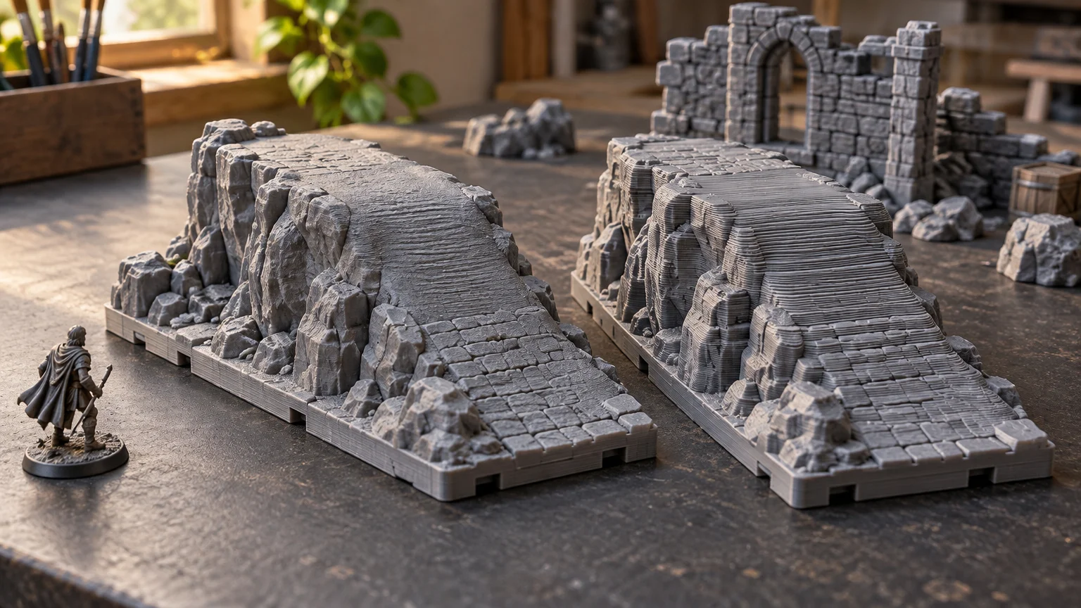
TLDR: Adaptive layer height is most useful on terrain with visible slopes, curves, arch crowns, domes, and irregular rock faces. It lets the slicer use thinner layers where vertical stepping would be obvious and thicker layers where extra Z resolution contributes little. Do not assume it will automatically shorten every print. Start with a trusted normal profile, generate the variable profile, inspect the sliced result, and compare its estimated time and visible layer distribution with a fixed-height version.
The main value of adaptive layer height terrain slicing is selective resolution. A sloped roof may benefit from fine layers near its shallow upper pitch, while the vertical walls below it may not. A boxy dungeon room, on the other hand, may gain little from the added complexity. The decision should be driven by geometry and sliced preview rather than by treating adaptive layers as a universal quality switch.
What adaptive layer height actually changes
A fixed profile slices the model at one nominal layer height, apart from special cases such as the first layer. Adaptive or variable layer height changes the thickness of successive layers according to the model’s shape. CuraEngine describes the underlying process as determining layer Z positions from model geometry, while PrusaSlicer and OrcaSlicer provide automatic and manual controls for shaping that profile.
This primarily changes vertical, or Z-axis, resolution. Thin layers can reduce the stair-step appearance on curves and shallow slopes, but they do not create extra XY detail simply because the layers are finer. An embossed stone pattern running across a vertical wall remains constrained by the model, nozzle, extrusion width, motion, and other profile choices. Prusa’s documentation likewise distinguishes smoother curves from XY features parallel to the build plate.
That distinction matters for terrain. Adaptive layers may improve the silhouette of an arched window without making every brick face sharper. They may make a roof pitch look less terraced without fixing stringing beneath the eaves. Think of the feature as selective control over vertical stepping, not as a replacement for a smaller nozzle, better orientation, calibrated extrusion, or suitable support settings.
Terrain shapes that are worth comparing
The strongest candidates combine visible upward-facing slopes with enough model height for the slicer to vary the profile meaningfully. Run an adaptive preview comparison when a piece includes:
- Sloped roofs, especially pitches that become shallow relative to the build plate
- Domes, towers, rounded battlements, or curved facade details
- Arched doors and windows where the crown will remain visible
- Rock faces, hills, craters, or cliff formations with broad angled surfaces
- Curved stairs, pipes, roots, or other features whose contours change through Z
- Large decorative transitions between vertical and near-horizontal surfaces
By contrast, vertical walls, flat floors, rectangular slabs, boxy rooms, and simple columns often give the adaptive tool little useful work. Their major surfaces are either vertical or horizontal, so reducing selected layer heights may not produce a meaningful tabletop difference. A proven fixed profile is usually easier to repeat across a large batch of modular pieces.
Texture also changes the decision. A rough cliff can visually disguise layer stepping, while a smooth plaster dome may expose it. Deep, intentionally irregular relief may benefit less than a broad, clean curve. If texture design is the larger concern, see how texture depth affects printable terrain detail rather than expecting variable layers to recover geometry that is absent or poorly oriented.
Begin with a trusted normal profile
Do not build an adaptive setup by choosing arbitrary minimum and maximum values in isolation. Start from a normal printer, nozzle, and material profile that already gives acceptable first layers, extrusion, cooling, bridging, and wall quality. Prusa recommends selecting a profile close to the layer height expected for most of the model because a print profile can change settings beyond layer height, including extrusion width.
The active printer or extruder profile should also define the usable layer-height limits. OrcaSlicer documents that its minimum and maximum layer-height settings constrain the adaptive tool. Its general guidance places layer height within an approximate range of 20% to 80% of nozzle diameter, while warning that extremes can introduce flow-quality or adhesion tradeoffs. Treat that as a broad software guideline, not a terrain recipe: the safe working range still depends on the machine, hot end, nozzle, material, speed, flow, and profile.
If the base setup is still uncertain, establish it before adding variable layers. The broader tabletop terrain printer settings framework explains how layer height interacts with walls, infill, supports, nozzle size, and the printer’s established material profile.
A practical slicer workflow
- Slice the model once with a trusted fixed-height profile. Record the slicer’s estimate and inspect the relevant slopes, curves, overhangs, supports, and connection areas.
- Enable the slicer’s variable or adaptive layer-height tool. In PrusaSlicer this workflow supports automatic generation, manual editing, and smoothing; OrcaSlicer provides comparable quality-and-speed, smoothing, and manual adjustment controls.
- Generate a moderate automatic profile first. Avoid immediately pushing the control toward maximum quality, because that can assign fine layers across more of the model than the visible surfaces justify.
- Inspect the layer-height graph and color visualization. Look for fine layers around the roof pitch, arch crown, dome, or curved rock surface that motivated the change.
- Apply smoothing only if the generated profile contains abrupt changes that need refinement. Smoothing changes the layer profile; it does not repair unsupported geometry or poor calibration.
- Slice again and compare the estimate with the fixed baseline. Also compare material use, layer distribution, support contacts, and any changes to how overhangs or bridges are divided.
- For a long or repeated print, consider validating a representative section or smaller piece before committing to an entire building or terrain batch. The goal is to check the chosen profile on your own machine, not to assume the preview guarantees a physical result.
The official Prusa variable layer height documentation provides a useful visual explanation of automatic generation, manual edits, and smoothing. Interface details differ by slicer and can move between versions, but the underlying workflow remains the same: establish a baseline, generate the variable profile, inspect it, and compare.
What to inspect in sliced preview
A successful slice is not merely one with many thin layers. It is one where thin layers appear in useful places without creating unnecessary time or new print risks. Review the model layer by layer, concentrating on these terrain-specific areas:
- Roof pitches: Check whether fine layers follow the visible shallow slopes rather than covering the entire building.
- Arches and domes: Inspect the crown, where stepping is often easiest to notice, and the underside, where overhang behavior still matters.
- Cliff faces: Decide whether the altered layer pattern improves an important silhouette or merely adds resolution to intentionally rough texture.
- Eaves and bridge spans: Variable layers do not eliminate the need to review bridging, cooling, or supports.
- Support contacts: Look for changes in the layers around supported undersides and interfaces. Do not assume a finer model layer automatically creates a clean support separation.
- Connectors and mating features: Inspect whether layer transitions occur through a fit-critical region. Adaptive layers do not correct XY dimensions or an unsuitable tolerance.
- Top surfaces: Confirm that the transition into shallow upper surfaces is sensible and that the chosen top-shell strategy remains appropriate.
- Estimated time: Compare the complete adaptive slice with the same model and orientation at fixed height. The estimate, rather than the feature’s name, tells you which version the slicer expects to finish sooner.
Where adaptive layers save time—and where they show
Adaptive layers can save time relative to printing the entire model at the finest layer height used on its curves. For example, a building could use finer layers around a rounded roof while retaining thicker layers through plain vertical wall sections. That is the useful comparison: adaptive versus an all-over fine profile capable of similar Z resolution on the critical curve.
They do not necessarily save time relative to a sensible fixed-height terrain profile. If the automatic tool marks much of a complex rock face for thin layers, the adaptive estimate can exceed the fixed baseline. Smaller layers require more passes through the same model height, and Prusa notes the associated tradeoff between smoother curves and longer print time.
Variable layers can also become visible when transitions are abrupt or when the model’s surface finish makes changes in layer rhythm easy to see. A transition may be less noticeable on irregular stone than on a smooth wall. Review the profile graph for sudden jumps, then use smoothing or restrained manual edits if the slicer provides them. Do not add fine zones merely to make the graph look uniform; each change should serve a visible part of the model.
Common problems and practical responses
The estimate became much longer
Move the quality-and-speed control toward a less aggressive setting and regenerate the profile. Check whether small decorative details caused large vertical ranges to receive fine layers. If most of the piece is already curved, a fixed compromise may be simpler.
Stepping is still visible
Confirm that the fine layers actually cover the relevant Z range. Then consider the surface angle, orientation, nozzle and extrusion width, and the model’s own geometry. Adaptive layers can reduce Z stepping, but they cannot make a low-detail mesh smooth or add nozzle-limited XY resolution.
The layer profile changes too abruptly
Apply limited smoothing and inspect the result again. Manual editing can help isolate a prominent roof or arch, but extensive edits make the profile harder to understand and reproduce. If the automatic result requires constant correction, a fixed profile may be the more dependable production choice.
The underside still looks difficult
Revisit orientation, overhangs, bridges, and supports. Variable layer height is not adaptive bed leveling, and it does not change whether a strand has adequate support beneath it. Adaptive bed mesh is a separate printer workflow concerned with the build surface.
When fixed layer height is the better choice
Choose a fixed profile when the terrain is mostly vertical and flat, when you are producing a repeatable batch of modular parts, or when the adaptive preview offers no clear improvement at normal viewing distance. Fixed layers also simplify troubleshooting because every section uses the same nominal Z increment.
A fixed height is not the unsophisticated option. It is often the efficient choice for floors, straight walls, simple ruins, and storage-focused terrain sets. The more useful question is not whether adaptive slicing is technically available, but whether selective Z resolution improves a surface players will see without complicating a part they need to print repeatedly.
Frequently asked questions
Does adaptive layer height improve all terrain details?
No. Its main benefit is vertical resolution on slopes and curves. It does not automatically improve XY detail, repair a coarse mesh, correct extrusion, or make unsupported geometry printable.
Should adaptive layers replace a fine fixed profile?
Not automatically. Compare three things: the visible critical surface, the slicer’s estimate, and the complexity of the resulting profile. Adaptive slicing is most compelling when it concentrates fine layers on limited regions instead of applying them to the entire model.
Can variable layer height remove the need for supports?
No. Layer thickness can affect how geometry is divided vertically, but support needs still depend on orientation, overhang angle, bridging, cooling, material behavior, and the model’s design.
Is a smaller layer height always better for terrain?
No. Smaller layers can smooth curves but increase the number of layers and expected print time. For more context on choosing a practical baseline, see the guide to layer height for 3D printed terrain.
Use adaptive layers as a comparison tool
For the next curved roof, arch, dome, or cliff, slice a fixed baseline first. Then generate an adaptive version and inspect exactly where the slicer places thinner layers. Keep the adaptive profile only if it improves the geometry that matters at the table while maintaining an acceptable estimate and a comprehensible layer pattern. That preview-and-compare habit is more reliable than enabling variable layers on every terrain file by default.