
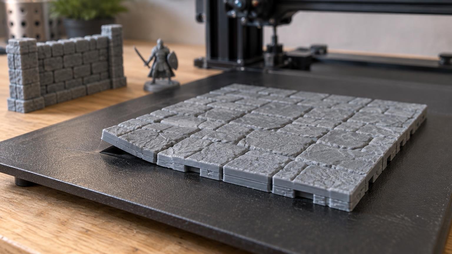
TLDR
For large terrain corners lifting, diagnose when and where the movement begins before adding a brim. Failure on the first layer points toward surface preparation, leveling, mesh compensation, Z offset, or an unsuitable profile. Lifting after a good start is more consistent with shrinkage, drafts, uneven thermal conditions, or cooling. Failure at one physical bed location suggests a local printer or surface issue. If only sharp model corners lift, a conventional brim or targeted brim ears may be an efficient mitigation—but they are not a substitute for correcting an unreliable first layer.
Large dungeon floors and building foundations put a long lever between each corner and the center of the print. As deposited plastic cools and contracts, stress can concentrate at those outer points. Prusa describes warping as corner lifting associated with temperature differences and material shrinkage, with larger prints particularly susceptible. Its warping troubleshooting guide also emphasizes surface condition, first-layer adjustment, profiles, cooling, and ambient stability rather than treating a brim as the only answer.
Identify the failure before changing settings
“The corner lifted” can describe several different failures. Pause the print when safe, note the layer or approximate stage at which movement appeared, and record whether the nozzle later struck the raised area. Also check whether the entire object moved or only one edge curled upward. Inadequate build-plate adhesion can progress from visible warping to a shifted or completely detached print, so an early corner problem is worth addressing before committing to another long terrain job.
| Observed pattern | Most useful first investigation | Likely response |
|---|---|---|
| Lines fail to bond or move immediately | Surface preparation, leveling or mesh, Z offset, correct profile | Establish a consistent first layer before using extra adhesion geometry |
| Base begins flat, then corners rise later | Material profile, drafts, ambient stability, bed conditions, cooling | Reduce the temperature gradient or shrinkage stress appropriate to the material |
| The same physical area of the bed fails | Local contamination, mesh error, airflow, plate condition, temperature uniformity | Test the location and correct the local cause rather than changing every object |
| Only sharp exterior model corners lift | Corner geometry and stress concentration | Use brim ears, a targeted brim, or a modest outer brim after confirming the first layer |
| Whole part breaks free | Widespread adhesion failure or severe warping | Stop and restore dependable bed contact before another full print |
If lifting starts on layer one, fix the first layer
A brim cannot rescue filament that is being placed inconsistently. Start with the printer-and-filament profile intended for the machine, nozzle, and material. If you recently imported a profile or changed nozzle size, verify those selections before tuning individual values.
Clean the build surface according to its manufacturer’s instructions. Different plate coatings and materials have different cleaning and adhesive requirements, so avoid applying an arbitrary solvent, scraper, or glue recipe. Inspect the plate under angled light for fingerprints, residue, damage, or a worn patch where large models are commonly positioned.
Then watch a simple first-layer test across the intended footprint. The lines should remain attached and join consistently without being dragged around by the nozzle. Gaps between neighboring lines can indicate insufficient contact; rough ridges or an overly plowed surface can indicate excessive compression. Prusa specifically recommends checking first-layer adjustment while warning that excessive squish can produce overly strong adhesion with some surface-and-material combinations.
Do not change bed temperature, nozzle temperature, fan behavior, Z offset, and flow simultaneously. Make one diagnosis-driven adjustment, repeat the small test, and record the result. That preserves cause and effect and costs far less time than using a full dungeon floor as the calibration object. For a broader baseline, compare your profile with these starting settings for tabletop terrain.
If a sound base lifts later, investigate thermal conditions
A base that looked good for several layers but curls later is not the same problem as loose first-layer lines. The first layer had enough initial grip, but contraction in the growing part eventually generated more force than the corners could resist.
Restore a known-good material profile before improvising temperatures or fan percentages. PLA, PETG, ABS, ASA, and other materials do not respond identically to cooling or ambient conditions. Prusa’s guidance treats cooling as material- and situation-dependent: PLA and PETG commonly require substantial cooling, while excessive cooling can worsen warping or layer adhesion in some circumstances. Higher-temperature materials particularly benefit from stable surroundings without drafts.
Look for environmental changes that coincide with the failure: an open window, room fan, air-conditioning vent, enclosure door, or a part-cooling change made in the slicer. A large terrain base can span areas exposed to different airflow. Correct the obvious asymmetry first instead of reflexively turning the fan fully up or fully down.
An enclosure can improve ambient stability for materials whose manufacturer recommends it, but it is not a universal upgrade for every printer or filament. Check the printer and filament makers’ current instructions, especially where electronics, softening temperatures, ventilation, or material emissions are relevant.
Treat repeatable bed-location failures as local problems
If different models lift whenever a corner occupies the same physical spot on the plate, the STL is probably not the first suspect. Rotate or reposition a small test shape so it covers the questionable area. Do not use a long production print for this check.
Inspect local surface condition, bed mesh or leveling behavior, airflow, and plate seating. Also consider whether the printer can maintain reasonably uniform conditions across the required footprint. A global temperature increase may make other areas unnecessarily aggressive while leaving contamination, a damaged surface, or a mechanical inconsistency unresolved.
This location test also helps separate printer problems from geometry problems. If the lift follows the model’s sharp corner after rotation, examine the model and slicing strategy. If it stays at the same bed coordinate, continue investigating the machine, plate, and environment.
Brims for large terrain corners lifting: choose the narrowest tool
Once the first layer is consistent and the environment is appropriate, a brim can add useful contact area around a vulnerable footprint. Prusa describes a brim as an extension of the first layer that increases build-plate contact, and its slicer permits brim settings to be adjusted by object.
Use a conventional outer brim for broad edge stress
A full outer brim makes sense when several edges need reinforcement, the base has a large continuous outline, or the model has repeatedly shown distributed lifting. It costs extra material and cleanup, and it may leave an edge that needs trimming before terrain modules sit tightly together. Check connector faces, tile seams, and stackable edges after removal.
Use brim ears for isolated sharp corners
When the center and long edges remain flat but two or four sharp corners rise, brim ears—also called mouse ears—can concentrate extra contact where stress is highest. OrcaSlicer documents conventional brims, automatic brims, and brim ears, although availability and terminology can vary by installed version.
Targeted or painted brims, where supported, serve a similar purpose. They reduce cleanup around doors, connector sockets, interior courtyards, and detailed perimeter textures. The practical goal is not the largest possible brim; it is enough extra contact at the locations that actually need it.
Keep the brim-object gap functional
The brim-object gap controls separation between the part and brim. More separation generally makes removal easier, but it also weakens the brim’s connection and therefore its adhesion benefit. If the brim peels away cleanly while the corner rises independently, the gap may be too generous for the intended job. If removal damages the base, verify that the first layer is not excessively compressed before adjusting the gap.
When geometry or orientation deserves attention
Sharp bottom corners are more prone to warping, while a larger bottom contact area generally improves adhesion, according to UltiMaker’s FFF design guidance. This does not mean every terrain base should be rounded heavily. A large radius can disrupt tile alignment, wall placement, or the visual line between modular pieces.
A small underside treatment, sacrificial corner tab, or removable ear may preserve the visible gaming edge while reducing stress concentration. Consider geometry changes when the same model corner fails across known-good printer setups or when the terrain can accept the change without compromising grid dimensions, connector fit, stacking, or table layout.
Changing orientation is worthwhile only if the new position retains adequate bed contact and does not create worse supports, weak layer orientation, visible scarring, or inaccessible cleanup areas. For large flat floors, standing the part at an angle can exchange warping risk for a tall, support-heavy print with weaker or rougher playable surfaces. Review the broader causes in the guide to stopping large terrain prints from warping before redesigning an entire terrain family.
A controlled retry checklist
- Classify the failure as immediate first-layer trouble, later warping, local bed failure, sharp-corner lift, or complete detachment.
- Return to the correct printer, nozzle, and material profile.
- Prepare the build plate using its manufacturer’s current instructions.
- Run a small first-layer or location test over the affected region.
- Remove obvious drafts or uneven airflow and use material-appropriate cooling.
- Retry with one measured change at a time.
- Add a full brim only for broad edge stress; prefer ears or targeted brims for isolated corners.
- Inspect the finished base for flatness, connector fit, damaged edges, and reliable placement on the gaming table.
Frequently asked questions
Should I raise the bed temperature when a terrain corner lifts?
Not automatically. First identify whether the corner failed immediately or lifted later. Confirm the material profile and compare it with the printer, plate, and filament manufacturers’ guidance. Raising temperature cannot clean a contaminated surface, repair a damaged plate, or correct a poor mesh.
Should I reduce the part-cooling fan?
Only when the material guidance and failure timing support that change. Restore a known-good profile first. Too much cooling can contribute to contraction or weak layer bonding in some situations, while insufficient cooling can create other dimensional and surface problems.
Are brim ears better than a normal brim?
They are more efficient when isolated sharp corners are the only vulnerable areas. A continuous brim is more suitable when lifting occurs along several edges or around much of the footprint. Neither option replaces first-layer and environmental diagnosis.
Can adhesive solve every corner-lift problem?
No. Adhesive compatibility depends on the build surface and material, and some products act as release layers rather than simply increasing grip. Follow the plate and printer manufacturers’ instructions. Do not use extra adhesion to conceal nozzle contact, leveling errors, severe drafts, or a damaged surface.
Fix the pattern, not just the raised corner
The best next step is determined by timing and location. Repair immediate first-layer inconsistency before touching brim settings. Investigate shrinkage, airflow, and material-specific cooling when a good base curls later. Treat a repeatable bed coordinate as a local machine or surface issue. Reserve full brims for broad stress and use targeted ears when sharp corners alone need reinforcement.
That diagnostic approach protects more than the current print. It produces flatter floors, better-fitting modular seams, more stable buildings, and fewer rough edges to clean before the terrain reaches the table.