
TLDR
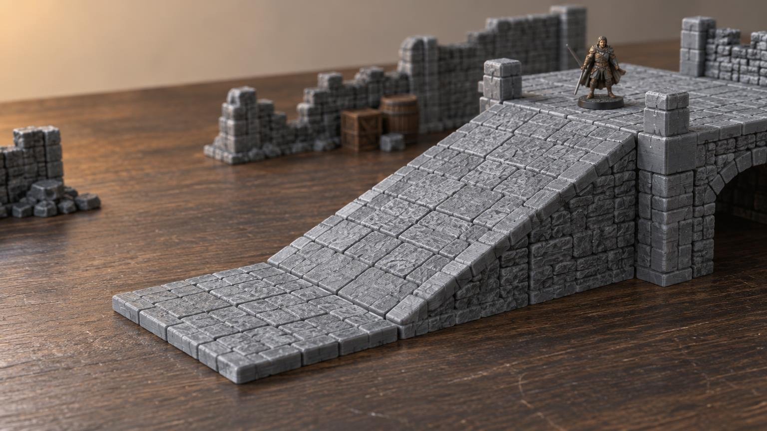
Good modular terrain ramps must do three jobs at once: connect known elevation levels, hold miniatures securely, and fit into layouts without consuming more playable space than the elevation is worth. Start by matching the ramp to your terrain family’s landing height, footprint or grid, orientation, and connection method. Then test one ramp with the miniatures you actually use before printing a full set.
The most important design choice is not simply making the slope shallow. A longer ramp may improve miniature stability, but it also occupies more table space. A short, steep ramp saves room but can make bases slide, overhang, or collide at the transition. The useful solution is a complete route: approach space, ramp, level landing, and a secure connection to the elevated section.
What makes a terrain ramp modular?
A fixed scenic slope is usually designed for one hill, building, or display board. A modular ramp is a repeatable transition component that can move between compatible platforms, risers, bridges, walls, or elevated encounter areas. Its value comes from predictable interfaces rather than from being a standalone model.
Those interfaces include the height at the upper end, the width of the route, the shape of the footprint, and any connector or alignment feature. Modular terrain is commonly organized around repeatable units and connection points, and the chosen connection method affects how securely neighboring components remain aligned. That principle does not imply compatibility between different publishers or terrain families.
Treat a ramp as part of a system, not an isolated scenic object. Before adding one to an existing collection, verify all of the following:
- The ramp reaches the exact elevation of the intended platform or riser.
- Its footprint fits the collection’s grid, tile pattern, or freeform spacing.
- Its upper and lower edges leave enough room for the miniature bases used in the game.
- Its connector style, polarity, orientation, and tolerance match the adjoining pieces.
- The intended print orientation and support requirements are documented for that specific model.
- The completed route can be assembled, moved, and separated without stressing small details.
Choose slope and length around miniature stability
There is no universal best ramp angle. Miniature stability depends on the slope, base diameter and shape, miniature height, weight distribution, surface texture, and how often models must remain on the incline. A top-heavy miniature on a smooth base can behave very differently from a low, wide model even when both technically fit the route.
Use a simple physical test. Place a representative small model, a typical model, and the tallest or most top-heavy model you expect to use at the lower, middle, and upper portions of the ramp. Gently handle the neighboring terrain as you would during play. The goal is not to simulate an impact; it is to identify whether normal miniature placement or table movement causes sliding or tipping.
Inspect the transition edges as carefully as the main slope. An abrupt lip at the top can prevent a base from sitting flat while its center crosses onto the landing. A pronounced lower edge can create a similar problem at table level. Smooth geometric transitions usually matter more during play than adding extra texture to the middle of the ramp.
Surface texture presents a tradeoff. Shallow relief can help bases resist sliding and make the route visually readable. Excessive relief may cause bases to rock, interfere with movement measurement, collect drybrushing unevenly, or become fragile at the edges. Texture should support the route rather than turn it into an obstacle course.
Base size means both the ramp footprint and the miniature base
When planning modular terrain ramps, “base size” can refer to two separate constraints. The first is the ramp’s footprint on the table. The second is the miniature base that must stand on it. Both need to work before the ramp is useful.
For the terrain footprint, ask how much horizontal space the ramp consumes relative to the playable area it unlocks. A long approach may be appropriate beside a large platform but awkward in a compact dungeon room. Turning or segmented routes can fit a smaller overall area, although every additional joint introduces another alignment point and another possible interruption to miniature placement.
For miniature clearance, do not check width alone. Test whether a base can sit flat near side walls, railings, rocks, posts, or connector housings. Also check whether two models can pass or stand together if the rules and encounter design expect that route to support them. A ramp can look wide in a slicer while decorative edges reduce its usable width substantially.
Build an access kit instead of printing one ramp repeatedly
A flexible elevation kit usually needs roles rather than dozens of unique pieces. Begin with the smallest verified selection that can create complete routes. If the relevant terrain family provides them, useful roles may include straight approaches, direction changes, level landings, raised platforms or risers, and system-specific connection parts.
The landing is especially important. It gives a miniature a level place to stop, allows a route to change direction, and separates two slopes that would otherwise meet at an awkward ridge or valley. It can also make an elevated objective easier to identify and handle.
This collection-first approach is similar to planning a broader terrain library: print pieces that combine into encounters instead of accumulating unrelated models. The guide to starting a 3D printed terrain collection without printing too much provides a useful framework for deciding which functional pieces deserve duplicates.
Plan a few repeatable layouts
Reusable terrain becomes faster to deploy when you document several proven configurations. Planning the floor layout and room flow before building is a common recommendation for modular dungeons, and the same principle applies to elevated routes. Start with the available footprint and desired play pattern, then place ramps rather than trying to force printed pieces into an improvised gap.
Four practical layout concepts are worth testing, provided your verified pieces support them:
- Raised objective: one platform with enough approach and landing space for models to interact around it.
- Two-access platform: ramps on different sides so the elevation does not become a single unavoidable chokepoint.
- Bridge approach: a ramp and landing at each end, with alignment checked across the complete span.
- Split-level area: multiple low transitions that distribute movement instead of concentrating every model on one tall route.
Photograph each successful configuration from above and record which pieces it uses. A simple label such as “two straight ramps, two landings, one platform” makes setup repeatable without requiring a custom tray for every arrangement. An overhead sketch can also show where miniatures are expected to stand, which reveals dead space that a scenic photo might hide.
Agree on terrain rules before play begins
A physical ramp does not automatically determine how a game treats movement, cover, line of sight, or elevation. Those effects depend on the ruleset and on any pre-game terrain agreements. Decide whether models can stop on the slope, whether the route changes movement, how edges affect cover, and what happens if a base cannot physically balance where its movement would end.
For example, the official Star Wars: Legion terrain rules direct players to define how custom terrain will be treated, including relevant cover and movement difficulty, before using it on the battlefield. That guidance is specific to Legion, but it illustrates why groups should classify custom terrain before a game rather than resolve every question mid-turn.
Use clear visual cues where possible. Consistent ramp textures can indicate walkable routes, while walls or railings can identify blocked edges. If the physical model and game rule differ—for example, if models may traverse a slope but cannot safely remain on it—agree on a marker or temporary placement method.
Print one fit-check piece before committing to a set
A ramp combines long contact surfaces, visible slopes, transition edges, and sometimes connectors. That makes a single test print more informative than assuming a general terrain profile will suit every design. Consult the model-specific documentation first, then evaluate the printed part rather than chasing one universal slicer setting.
Check these points on the first print:
- Base flatness: the ramp should sit without rocking or lifting at a corner.
- Landing height: the upper edge should meet the intended platform without a step or gap that disrupts base placement.
- Connector fit: joints should be secure enough for handling but removable without bending the ramp.
- Usable clearance: representative miniature bases should fit between decorative boundaries.
- Slope finish: layer artifacts, support scars, or stringing should not create unstable contact points.
- Weak sections: thin rails, pegs, and layers near connector pockets should tolerate ordinary assembly.
- Paint allowance: primer and paint should not turn an already tight joint into a permanent connection.
Curved or changing slopes may benefit from finer layers only where the added resolution is visible or improves the transition. Adaptive layer height for terrain explains how to concentrate finer layers on curves and slopes without applying them to the entire print. Compare any adaptive result with a dependable fixed-layer baseline and inspect whether layer transitions become visible.
Organize ramps for quick setup and safe storage
Store ramps by compatibility family and elevation, not merely by appearance. Two stone-textured pieces may look related while using different landing heights or connectors. Labels on bins or trays can identify the terrain family, height level, route width, and connector type without requiring permanent marks on painted surfaces.
Keep small connection components in a closed, labeled container inside the same larger bin. If connectors have orientation or polarity, include a reference piece or diagram. Avoid packing heavy platforms on top of thin railings or steep ramp edges, and separate painted faces if rubbing during transport could damage the finish.
During breakdown, remove miniatures first, disconnect the elevated route from its outer ends, and support long sections instead of lifting an entire assembly by one ramp. This reduces leverage on connectors and makes it easier to notice a component that has become unusually tight.
Frequently asked questions
Should miniatures be able to stop on a terrain ramp?
Ideally, a route intended for regular movement should support the miniature bases used in the game. Whether models are allowed to stop there remains ruleset-specific. If the design cannot hold them safely, establish a consistent placement convention before play.
Are shallow ramps always better?
No. A shallow slope may improve stability but requires a longer footprint. On a crowded table, that can remove useful movement space or make the elevated feature difficult to position. Choose the gentlest slope that fits the available area and passes the miniature test.
Can ramps from different terrain sets be mixed?
Only after verifying landing height, route width, footprint, connectors, and transition clearance. Similar texture or scale does not establish mechanical compatibility. An adapter or independent landing may sometimes bridge systems, but that should be evaluated as a new fit-check rather than assumed.
How many ramps should I print?
Print one and test it first. Then decide which documented layouts you want to build simultaneously. Duplicate functional pieces only when they unlock a second access route, complete another elevation, or materially speed setup.
Make the route work before adding more scenery
The best modular terrain ramps are not necessarily the longest, steepest, or most detailed. They are the ones that reach the correct height, hold the intended miniatures, connect without excessive force, and reappear in several useful layouts. Verify compatibility, print one test piece, build a complete table-level-to-platform route, and document the configuration. Once that route survives setup, play, and breakdown, you have a sound basis for printing duplicates or expanding the elevation system.